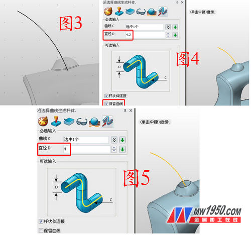
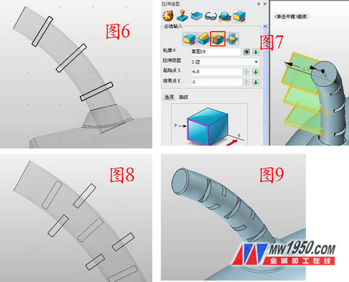
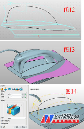
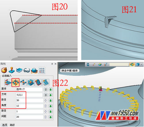
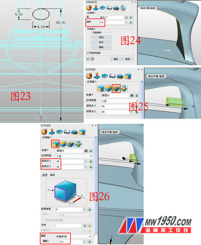
In the tutorial "Three-dimensional CAD crash tutorial: detailed explanation of the surface model of electric iron", Xiaobian has shared the surface modeling skills of the main part of the electric iron. Next, Xiao Bian will use Zhongwang 3D as an example software to help the friends who are learning 3D design to understand the basic functions of 3D CAD software by sharing the 3D CAD design process of the details of the electric iron. Interested friends can go to the 3D Technology Forum to download the 3D CAD drawings of the electric iron for free. Next, we will explain the modeling process of the details of the electric iron. 1. Insert sketch 1 on the XZ plane and draw a semicircle with a radius of 4. As shown in Figure 1, click on the rotation - add operation, the contour is sketch 1, the axis is the diameter of the semicircle, and the starting and ending angles are 0 and 360 degrees, respectively. Round the intersection edges, as shown in Figure 2. 2. Insert sketch 2 on the XZ plane, draw the curve shown in Figure 3, click on the rod sweep, curve select sketch 2, diameter is 4.2, note, tick before the "retention curve", as shown in Figure 4. Click on the combination - subtraction, subtract the swept cylinder to form a hole, click on the rod sweep again, select the sketch 2 for the curve, this time the diameter is 4, cancel the hook before the "retention curve", as shown in Figure 5. . Forming the effect of the wire extending from the hole. 3. Insert sketch 3 on the YZ surface, draw the three rectangles shown in Figure 6, exit the sketch, click on the stretch-subtraction operation, and stretch the sketch three times. The parameters are as shown in the figure, forming the effect shown in Figure 7. Select the "Retained Outline" below when stretching for the first time. Insert the sketch 4 on the YZ plane, draw the two rectangles shown in Figure 8, exit the sketch, click the stretch-subtraction operation, and stretch the sketch 4. The effect is shown in Figure 9. The rectangles in these two sketches can be roughly the same size. 4. Insert the sketch 5 on the YZ plane and draw the curve shown in Figure 10. You can click on the rod sweep to sweep the sketch 5 with a diameter of 3. The effect is shown in Figure 11. 5. Insert sketch 6 on the YZ plane, draw the two curves shown in Figure 12, and stretch the two curves of sketch 6 respectively (you can set the attribute filter to curve, so you can select the curve separately), as shown in Figure 13, click Split, the base is the lower shape, the split surface is the lower surface, and the shape is divided into two parts. Similarly, the handle is also divided into two parts. The purpose of this step is to prepare for the subsequent color setting. 6. Insert the sketch 7 on the XY plane, draw the circle shown in Figure 15, click the stretch - add operation, and stretch the sketch 7, as shown in Figure 16. Click Stretch, the contour is the upper circular surface of Figure 16, the stretching distance is 0.3, and the offset option is "Shrink/Expansion" offset is -7. For the same reason, stretch again, the parameters are as shown in Figure 18, and the edges are rounded, as shown in Figure 19. 7. Insert the sketch 8 on the YZ plane, draw the graph shown in Figure 20, click the stretch - the base, the stretch type selects the symmetry, the outline is the sketch 8, the end point is 0.15, the edge is rounded, the fillet radius 0.18, as shown in Fig. 21, click on the array - circular, the base is the tensile body of Figure 21, the direction is the axial direction of the cylinder, the number is 30, the angle is 12, as shown in Figure 22. 8. Insert the sketch 9 on the XZ plane and draw the ellipse shown in Fig. 23. The parameters are as shown in Fig. 23. Click on the surface-surface offset, and select the part shown in Fig. 24, offset by 0.8 to hide the offset surface. Click Stretch - Subtraction, the outline is sketch 9, the parameters are as shown in Figure 25. Click Stretch - Base, and then stretch Sketch 9, the parameters are shown in Figure 26. Note the selection of offset and offset. 9. Display the offset surface hidden in step 8. Click Trim. The base is the stretched body in step 8. The trimmed surface is the offset surface, as shown in Figure 27. Note that the white arrow points to the part to be retained. Round the edges of the body and the hole, as shown in Figure 28, click on the face properties to color the various parts of the shape. The effect is as follows. At this point, the 3D CAD modeling of the various parts of the electric iron is completed. Combined with the appearance of the body surface of the electric iron, the 3D design beginner can get familiar with a complete 3D CAD operation process more quickly. If you have any questions in the process of self-study, you can go to the 3D expert training section of the Zhongwang - follow the teacher to learn 3D to ask questions, the teacher will answer your questions in the first time, and the 3D CAD tutorial compiled by the teacher. To help you quickly master 3D design. Zhongwang 3D 3D CAD/CAM software Free download: Zhongwang official website Zhongwang 3D is the preferred brand of 3D CAD/CAM recommended by the Ministry of Industry and Information Technology for military enterprises. It provides cost-effective 3D CAD/CAM solutions for enterprises, modeling, mold, assembly, reverse engineering, sheet metal, 2-5 axis processing and other functional modules. Everything is available. Efficiently compatible with other 3D CAD software, easy to learn and use, integrated rich parts library, new learning tutorials and free download of massive quality 3D CAD drawings, etc., making it easier for you to master 3D design and machining programming. Download the latest version now and apply for free 3D CAD/CAM & 3D printing technology training. Paint Brush,Paint Brush Online,Oil Brush Photoshop,Paint Tool Sai Brush Laizhou Chenke trading Co., Ltd. , https://www.chenkegroup.com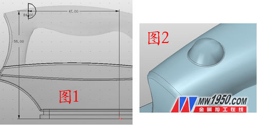


3D CAD Quick Start Tutorial: Explain the Modeling of Electric Iron Parts