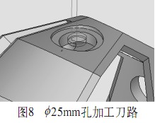
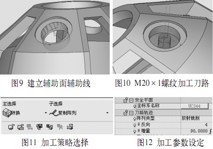
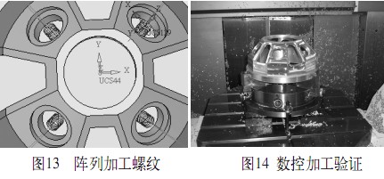
The CimatronE system is a CAD/CAM integrated software system developed by Cimatron of Israel. It uses the same database using parameters and variable feature modeling technology. It has modeling, assembly design, 3D marking, mold design, CNC machining and standard formwork. And other functional modules. CimatronE's CNC machining technology has always been at the forefront, and is considered by the world's mold industry to be one of the most outstanding CNC programming systems. CimatronE's powerful 3D modeling capabilities are used to create 3D models of typical parts through styling commands such as stretching, rotation, resection, and steering. The model built is shown in Figure 1. (1) Analysis of parts processing technology The inner and outer taper of this part has been completed by the previous turning process. The part is built on the basis of the section rotation, and the three-claw self-centering chuck is used for clamping. According to the structural analysis of this part, Determine the machining route of the part. The plane and the special-shaped hole on the outer taper of the part are processed by five-axis linkage. Four φ 25mm on the conical surface, a circular hole with a depth of 3mm, and a thread of M20×1 depth and 10mm are processed by five-axis positioning. . (2) Selecting the machining origin and establishing the coordinate system Considering the measurement of the workpiece and the convenience of tool setting and correction, the machining coordinate system is established at the geometric center of the upper surface of the workpiece. The established coordinate system is shown in Figure 2. (3) Tool setting Through the analysis of the machining process of the parts, the machined hole and the φ 25mm round hole are made of φ 16mm alloy knife. The φ 20mm×1 threaded bottom hole is machined by φ 10mm end mill and threaded with φ 11mm thread cutter. Four R3mm rounded corners on the profiled hole are machined with a φ 6mm end mill. (4) Planning the machining tool path Processing the contour hole plane: In order to facilitate the processing, the upper surface of the shaped hole is first completed, and the result of the complementary surface is shown in FIG. The plane of the shaped hole is processed: machining program / five-axis machining / general strategy / parallel to curve milling. The machining path is shown in Figure 4. Shaped hole machining strategy: machining program / five-axis machining / general strategy / copy milling between two curves. The actual machining material removal amount of the special-shaped hole is relatively large, and in order to improve the machining efficiency in the actual machining, the tool is an alloy knife of φ 6 mm. During roughing, the side wall of the shaped hole leaves a margin of 0.5 mm on one side, and the excess material is removed around the side wall of the shaped hole. The same method is used to remove the allowance of 0.5 mm on one side. The processing parameters are shown in Figure 5, and the machining path is shown in Figure 6. φ 25mm hole: Four φ 25mm holes are processed by five-axis positioning. First, the local machining coordinate system is established, and the coordinate system is established at the center of the upper surface of the M20×1 threaded hole, as shown in Fig. 7. Activate the local coordinate system. Since the φ 25mm hole has tolerance, it is processed in the order of coarse and fine. The machining strategy is: machining program / 2.5 axis / blank ring cutting, roughing: machining parameters side allowance 0.5mm, bottom margin 0. Finishing: The remaining margin of the machining parameters and the remaining amount of the bottom surface are 0. The machining path is shown in Figure 8. Threaded bottom hole processing: The M20×1 thread bottom hole is machined by five-axis positioning, and the coordinate system uses a local coordinate system for machining φ 25mm holes. Tool: φ 10mm end mill, machining M20 bottom hole φ 19mm round hole. Machining strategy for M20×1 threaded bottom hole: machining program / 2.5 axis / blank ring cutting. Thread processing: Four M20×1 threads are machined by five-axis positioning. Since CimatronE does not have a special module for milling threads, the auxiliary surface and auxiliary line are used to realize the thread processing. First make a φ 20mm auxiliary surface, and then make a spiral with a base radius of 10mm, a thread height of 10mm, a pitch of 1mm, and a reverse direction, as shown in Figure 9. Machining strategy for M20×1 threaded bottom hole: machining program/local operation/local three-axis/curve projection milling. The threading tool path is shown in Figure 10. Four M20×1 threads are evenly distributed on the conical surface of the workpiece. It is cumbersome to program the thread due to the method of auxiliary surface and auxiliary line. The other three are processed by the conversion function of Cimat ronE (see Figure 11 and Figure 12). ), the specific processing strategy: machining program / conversion / copying the entire column / tool path / radiation milling. The tool path is shown in Figure 13, and the NC machining verification is shown in Figure 14. With the continuous development of science and technology, multi-axis linkage CNC machine tools have become the most important processing tools in the processing industry. Multi-axis linkage CNC machine tools play an increasingly obvious advantage in the manufacturing field. Through the processing of this typical part. With conventional machining methods, multiple clamping must be performed, and the time for the clamping correction takes up a large proportion of the total machining time. Five-axis machining can be used to machine the special-shaped holes, undercuts, holes and threads with three-axis multiple clamping in one setup. It not only improves the machining accuracy of the parts, but also greatly improves the processing efficiency of the products. Bilateral Laser Distance Meter
A double side laser measure is designed for convenient and efficient measurement works. The easy-to-read digital screen displays the battery life, so you won`t be left without your measuring tool each time it is needed. You can bring it everywhere with you, and the smart functions that comes along with it is user-friendly for anyone, including beginners in DIY. It is the ideal multifunctional measuring tool that suit all users including home renovators, architects, interior designers, construction workers, or even DIY lovers.
bilateral laser distance meter,bilateral laser measure,double side laser measure,bidirectional distance measurer Chengdu ZT Electronics Technology Co., Ltd. , https://www.lasermeasuretool.com 1. Typical part modeling
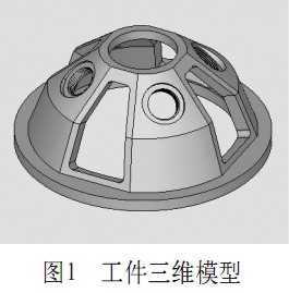
2. CNC machining
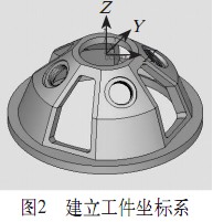
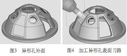
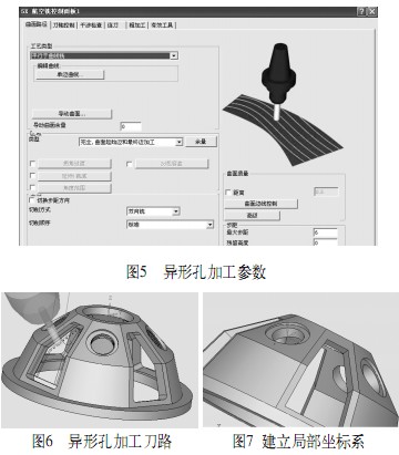
3. Conclusion
The bilateral laser measurer is a powerful, dual direction laser measuring tool that makes measuring building and rooms a simple task.
The two lasers allow you to stand in the center of a room find the distance between walls (even if the room is fully furnished) and between the floor and ceiling.
When using the bi-directional lasers, the device can be placed in Continuous Measuring Mode to help you find the center point of a wall or room. Interior designers will love how simple it is to perfectly mount paintings and decor in the center of a wall. This mode is also perfect for real estate agents who want to provide accurate measurements to homebuyers, without wrinkling their suit.
Perfectly measure for new blinds by finding the exact size of the window casings.
The single direction laser option measures from the opposite end of the device, allowing you to lay the device flush with walls for accuracy.
The device can display measurements in meters, feet, and tenths, or feet and inches, to give you the details you need to complete your task.
Design and five-axis machining based on CimatronE9 typical parts