1 Introduction Wooden Blades Ceiling Fan With Bulbs Brightest Light Bulbs For Ceiling Fans,Ceiling Fan Light Bulb Replacement,Ge Ceiling Fan Light Bulbs,Led Fan Bulbs JIANGMEN ESCLIGHTING TECHNOLOGY LIMITED , https://www.jmesclightingfan.com
With the development of the national economy, power users have higher and higher requirements for power supply quality and power supply reliability. Realizing distribution automation is the most effective means for power distribution systems to improve power supply reliability. In distribution automation systems, feeder automation is the basis of distribution automation systems. As the core terminal of the feeder automation system, the feeder terminal becomes the key to the successful implementation of the distribution automation system.
The feeder terminal is abbreviated as FTU (Feeder Terminal Unit), which is mainly used to monitor primary equipment such as load switches and reclosers on the column. Provide distribution system operating conditions and various parameters to the distribution master station/substation: including switch status, power parameters, phase and ground faults, and parameter information at fault time, and perform power distribution master/substation pairing Control and adjustment instructions for electrical equipment.
As an open bus with international standards and mainly designed for industrial sites, CAN bus has the advantages of high reliability, strong real-time performance, flexible networking and low cost. The CAN bus communication method in the feeder automation system has broad prospects. The reason why the CAN bus is used is mainly determined by the characteristics and performance requirements of the feed automation communication. In the feeder automation system, the number of feeder terminal nodes is large, the communication nodes are dispersed, the communication distance is short, the data volume is small, and the working environment is relatively bad; this requires the communication network topology to be flexible, easy to change, and can accommodate various communication media. It is easy to form a large network to facilitate network management; at the same time, it requires high reliability and real-time performance of network communication. The CAN bus, which is mainly used for low-level device communication, is fully applicable to this occasion.
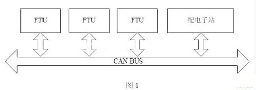
The feeder terminals described in this paper are mainly used for railway crossings to complete the monitoring of the feeder lines used to power the railway crossing signal lights. The structure of the entire system is shown in Figure 1. According to the characteristics of the CAN bus, we connect the electronic station and each FTU as a node on the bus to form a bus-type LAN through the shielded twisted pair. The working principle of the feeder terminal is that under normal operating conditions, the FTU monitors the operating parameters of the feeder line, uploads various operating parameters to the distribution station via the CAN bus, and receives commands from the distribution station to realize remote switching and branching of the line switch. Gate operation to optimize the distribution network. When the line fails, the FTU sends an alarm signal to the distribution station in time. After receiving the alarm signal, the electronic station will judge the corresponding fault phenomenon, isolate the fault section of the feeder line and restore the power supply to the non-faulty area, thereby reducing the power-off area and shortening the power-off time. The feeder terminal can work in real-time detection and monitoring according to the request of the electronic station: in the real-time detection working state, the feeder terminal sends the operation parameters of the feeder line to the distribution station in real time; while working in the monitoring state The feeder terminal periodically sends relevant parameters to the distribution station. In addition to the traditional three-way function, the FTU also has functions such as fault recording, over-limit active alarm, and SOE (event sequence recording). 
2 Hardware structure design of intelligent feeder terminal
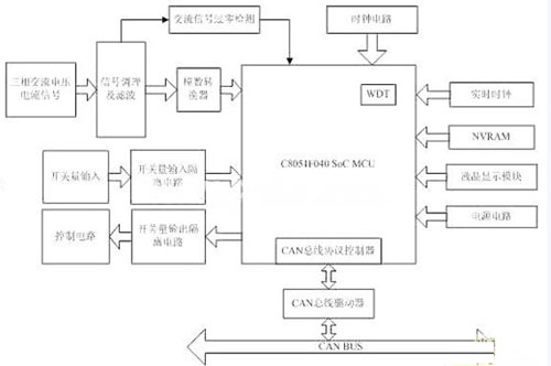
The FTU introduced in this paper is an all-digital control unit based on SOC type microcontroller. The whole device is divided into main control part, analog electric signal acquisition and conditioning part, digital input and output control part, CAN bus communication part, liquid crystal display human-machine interface part and so on. Its principle block diagram is shown in Figure 2. 
The main control part adopts C8051F040 (hereinafter referred to as F040) single-chip microcomputer. The F040 single-chip microcomputer is a fully integrated mixed-signal system-on-chip type microcontroller introduced by CYGNAL. It integrates almost all analog and digital peripherals and other functional components needed to form a single-chip microcomputer data acquisition on a single chip. At the same time, its operating speed is greatly improved compared with ordinary single-chip microcomputers, due to the use of pipeline technology. Its speed can reach 10 times of that of ordinary single-chip microcomputer. Users can construct a complete measurement and control system by simple configuration of corresponding registers and cross-switches on the chip according to actual needs, which is designed for small size, low power consumption and low. Cost, high reliability, high performance microcontroller application system provides great convenience.
The analog signal acquisition and conditioning part of the grid voltage and load current in the grid first through the field PT and CT conversion to 0-100V and 0-5A AC power, and then through the special secondary PT and CT conversion to 0-5V The voltage signal is then conditioned by the conditioning circuit to an acceptable measurement range for the ADC. The conditioned AC signal is passed through a first-order voltage follower and a second-order active low-pass filter to remove higher harmonics and noise signals into the ADC for measurement. . For railway applications, it is necessary to simultaneously measure the three-phase voltage and three-phase current of the two return lines (through and self-closing), and a total of 12 AC channels are required. To ensure simultaneous sampling of the AC voltage and current signals, and improve the sampling accuracy, we Two MAX125s from MAXIAM were used to do the job.
The digital input/output control part F040 has a total of 8 groups of 64 ports P0~P7, and each port is bit addressable. With such ample ports, we can easily connect the corresponding switches without having to expand the ports. The port is not directly connected to the associated switch, but through the corresponding optocoupler. The purpose of this is to prevent transient interference from the power grid. The F040 periodically detects the opening switch and transmits the corresponding value to the distribution station via the CAN bus to realize the remote signaling function. Receiving the control signal of the opening switch issued by the electronic station controls the opening and closing of the corresponding switch to realize the corresponding remote control function.
The frequency measurement part uses the hardware resources inside the F040. We can easily measure the AC power frequency signal. The specific implementation method is to take an AC signal, and after corresponding limiting processing, send the voltage comparator into the F040 chip to obtain a square wave signal. The voltage comparator in the F040 can adjust the hysteresis voltage, and the hysteresis voltage comparison function can be realized by adjusting the hysteresis voltage to eliminate the jitter phenomenon of the input signal at the zero-crossing point. The square wave signal output from the voltage comparator is connected to a capture/compare unit of the F040's on-chip PCA (Programmable Counter Array). The capture/compare unit operates in the upper edge capture mode. Each time the upper edge is detected, it will cause one. Interrupt, while generating a capture, the value of the PCA counter is now sent to the capture register of the capture/compare unit. We calculate the difference between the two captured PCA0 count values ​​in the interrupt service subroutine, which is the period corresponding to the AC power frequency. The PCA counter selects the same time base as the timing sample counter, so this count value can be divided by the number of samples to be used as the reload value of the timing sample counter for the next AC sample.
Research on Intelligent Feeder Terminal Based on CAN Bus