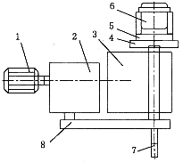
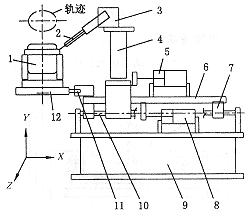
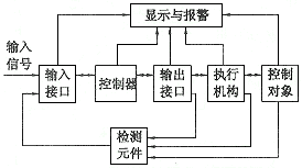
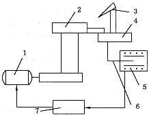
2.2 Table rotating parts <br> The table rotation is driven by a DC motor (400W , 1500r/min) via a reducer (i=1 : 380) , as shown in Figure 4 . The upper part of the workbench is a centering fixture, and its structure is the same as that of the double manipulator; the middle part is equipped with a contour cam to control the relative movement trajectory of the welding torch and the workpiece to form the required elliptic curve; Therefore, the lowermost end is a rotary air inlet joint, and the pressure gas is sent to the specific cylinder through the through hole of the spindle center. Figure 4 Schematic diagram of the workbench 2.3 Contour slide parts <br> The structure diagram of the profiling slide is shown in Figure 5 . The welding gun is mounted on the welding gun positioning device and can be moved in the X and Y directions and in the Z direction to adjust the optimal inclination and arcing distance of the welding torch to ensure the quality of the weld. The fast-forward and retreat bracket can be moved 50mm along the guide rail under the driving of its cylinder to facilitate the loading and unloading of the workpiece. The joint surface of the upper and lower shells of the compressor is an ellipse. When the workpiece rotates around its center, its radius R is a variable value, so the torch needs to be displaced in the X direction. The pressure roller and the slide plate are in the contour cam and Under the control of the contour cylinder, the required displacement is achieved to form an elliptical trajectory. Figure 5 Sketch diagram of the profiled slide table 3 pneumatic transmission system In addition to the DC motor used in the rotation of the table, the welding equipment uses pneumatic transmission. Among them, 7 cylinders are imported parts, and 3 cylinders are designed and manufactured by themselves. The following is a brief description of some components. The opening and closing of the two robots is detected by the FC1 and FC2 sensors. Only when FC1 and FC2 are ON , the robot is in the open position. There are three detection sensors FC7 , FC8 and FC9 at the indenter , FC7 and FC9 are piston motion limit position sensors, and FC8 is the head work position sensor. Welding can only be performed when FC8 is ON; when FC9 is ON , it indicates that there is no workpiece on the centering fixture and immediately alarms. 4 electronic control system The control system is controlled by Siemens PLC and the outputs are operated by intermediate relays. The PLC has 8 input modules and 5 output modules. The input module mainly includes power supply 110V output, manual / automatic selection, various alarm inputs, two-hand start button, welder on, fault reset, air pressure detection, and feedback of each actuator position signal. The output module includes a turn-on welder, a workpiece count, a forward-reverse delay, and a drive of each actuator solenoid valve. The block diagram of its control system is shown in Figure 6 . Figure 6 control system block diagram As mentioned above, the upper and lower shell joint trajectories are an ellipse. In order to ensure the quality and uniform weld thickness during the whole week of welding, it is necessary to ensure that the linear velocity of the joint at the joint relative to the elliptical center is substantially constant. When the solder joint is at the short or long axis, the line speeds are quite different. In order to solve this problem, we adopted a DC speed control system, and through experimentation, selected several discrete points ( as shown in Figure 7 ) , that is, several variable speeds were selected to meet the actual production requirements. To this end, a set of LED detection devices was developed, which cooperated with the thyristor speed control device to solve the problem of weld trajectory satisfactorily. The detection device is non-contact type, and has the characteristics of reliable performance, long service life and good speed regulation performance compared with the gear and pinion potentiometer type detection device used in foreign equipment. The schematic diagram is shown in Fig. 8 . Figure 7 workpiece shift point map Figure 8 Schematic diagram of speed control Under the control of the profiling cam, the contour sliding table moves the visor on the visor, and the number of diodes blocked at different positions is different, thereby converting into electrical signals of different amplitudes, inputting into the thyristor DC speed regulating device, and controlling the direct current. The speed of the motor. 5 Conclusion The successful development of the sealed shell automatic welding machine has made the production of refrigerator compressors a step toward automation, greatly improving the quality and productivity of the products, reducing the labor intensity of workers, and significant economic and social benefits. The key technologies of its mechanical systems and control systems are also applicable to a variety of non-circular curved shell products. Previous page wire holder is made of high quality 304 stainless steel, It is easier to clean without rust, safe, healthy and durable, Prevent rust or chemicals from contaminating food and damaging health. Suitable for putting the wine glass holder. Goblet Rack,Stainless Steel Goblet Rack,Wine Glass Holder,Wine Glass Rack Shenzhen Lanejoy Technology Co.,LTD , https://www.wirefruitbasket.com
1. Motor 2. Reducer 3. Base 4. Profile cam 5. Centering fixture
6. Workpiece 7. Rotary intake joint 8. Synchronous toothed belt 
1. workpiece 2. welding torch 3. welding gun positioning mechanism 4. fast advance and retreat bracket
5. Fast forward and backward cylinder 6. Skateboard 7. Bearing seat 8. Profile cylinder 9. Support
10. Guide shaft 11. Pressure roller 12. Cam
A pressure reducing valve is arranged in the pressure head circuit, and the pressing force of the pressure head can be adjusted through the valve, so that the upper and lower casings are tightly closed without subjecting the centering clamp to excessive pressure.
The function of the pressure relay in the contour loop is: when the equipment is maintained, the torch is retracted by the manual reversing valve; after the work is put into operation, the manual reversing valve should be connected to the contour air pressure; when the air pressure is 0 , the whole machine cannot Work to prevent accidents due to misuse. The pressing force of the contouring head and the contour cam is adjusted by the pressure reducing valve in the circuit.
A pressure relay is also installed in the main circuit. When the air pressure is insufficient, the control system alarms and stops welding. The reversing valve used in the system is manually operated except for the contoured circuit, and the other circuits are all equipped with electromagnetic reversing valves. 


1. DC motor 2. Profile cam 3. Welding torch 4. Profile slide
5. Light-emitting diode 6. Light-shielding plate 7. Speed ​​control device
China leading manufacturers and suppliers of Wine glass holder,Goblet Holder, and we are specialize in Wine Rack,Hanging Wine Rack, etc.
Research on Sealed Shell Automatic Welding Machine (2)