Inser bearings & Units/Mounting Bearing Units:
Inser bearings have many series, there are UC, SA, SB, HC, SER, UK,
UEL, UD SC series, the bearing Housings have P, PK, AK, PH, F, FS, FL,
FT, FC, FA, T PP, PF, PFT, PFL series.the Clearance should be C3 grade.
Borine' Inser bearings are made with quality Chrome steel and the
Housings are made with Casting, are basis on good quality and
competitive prices.
We are manufacturer of Insert Bearing in China, if you want to buy Bearing Mounting, Pillow Block, please contact us.
Insert Bearing,Bearing Mounting,Pillow Block,Mounting Bearing Units NINGBO BORINE MACHINERY CO.,LTD , https://www.borine-agroparts.com
3. Height following the groove
Most external arc voltage adjustments can only have a fixed arc voltage setting throughout the cut. In the cutting program with different groove angles, all the different groove angles use the same arc pressure setting, which directly introduces considerable dimensional error. In order to make up for this defect, some systems change the arc voltage setting value in the NC program, but the disadvantage of this method is the lack of flexibility of on-site adjustment. For a large-scale cutting program, there is almost no parameter in the field modification NC program. Practical meaning. What came into being was the groove arc pressure heightening system. This system is built into the CNC and integrated with the NC program. Whenever the groove angle changes, the groove arc pressure height adjustment system automatically corrects the arc pressure setting value to achieve the best height following effect.
4. Original road retreat with groove angle
As with the plane cutting, the steel plate may not be cut through for various reasons in the middle of the groove cutting, and it is necessary to retreat to the uncut point. This is the original way back function for the cutting machine CNC. However, the difficulty in retreating the original path of the groove is that the angle of the groove on the retreat path should also be “retractedâ€, and the posture following the path should also be “retracted†to ensure that the groove cutting is performed at any retreat point. The correctness. Similar requirements include the recovery of the groove attitude at the break point after power failure recovery, etc. These functions bring great convenience to the groove cutting operation. A bevel cutter without this function is bound to have to end the program when the groove is retracted, and then return to the starting point to re-run to the uncut point, which is not practical in practice.
5. Groove path compensation
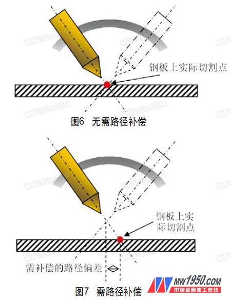
At present, the popular groove mechanism on the market includes a four-bar linkage represented by a small pool, a double pendulum mechanism represented by Faliley, a fitting angle mechanism represented by Messer, and a revolving represented by Isa. + Deflection mechanisms, as well as some other derivative designs on these institutions. But no matter which design, there is a problem of calibration of the groove center point. When the center of the swing of the groove angle deviates from the design center, the size of the groove cut must be wrong. In fact, this mechanical swing center is difficult to adjust, or it is difficult to maintain it after adjustment. An initial height adjustment will shift the actual swing center of the groove angle. Some high-end bevel cutting devices have servo motor-controlled fine-tuning mechanisms to compensate for such offsets. However, most bevel cutting systems must rely on a beveling CNC system to dynamically adjust the cutting path deviation according to the offset of the center of the swing, thus maintaining the cutting dimensions to maintain accuracy. There are also attempts to pre-compensate paths in programming, but their accuracy and flexibility are limited. Fig. 6 is a schematic diagram of the correct correction of the groove center without the path compensation, and Fig. 7 is a schematic diagram of the path compensation due to the initial height adjustment or the mechanical adjustment deviation. 
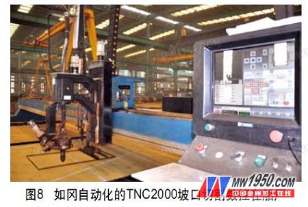
The bevel cutting system that effectively solves these critical problems has a large simplification and performance improvement in operation, programming and maintenance. Figure 8 is a photograph of an application example. 
Previous page 1 2
Several key technologies for groove cutting CNC cutting (2)
Another method is to pre-estimate the program size changes caused by these parameters according to different groove angles, and then implement them in programming. However, this method usually lacks the flexibility of on-site adjustment, and indirect estimation of the workpiece size is often difficult to grasp the accuracy.