1 Simulation and Simplification of the Structure 1.1 Introduction to the Real Bridge The bridge is a large-diameter concrete-filled steel reinforced concrete skeleton rib arch bridge located in Yunnan. The design load is: the automobile is over 20 grades, the main hole of the 120-level trailer is a 180m span upper-supported box rib arch bridge, the main arch box rib is a catenary arch with equal thickness, and the steel tube concrete forms a stiff skeleton. The cast-in-place arch-span ratio is 1/5.5, and the arch-axis coefficient is 2 24 arches. The road plate of the upper abdomen is a reinforced concrete hollow slab with a span of 125 m. The bridge construction is carried out in 4 steps: (1) 20 Section hoisting and closing the rigid skeleton steel pipe; (2) injecting No. 40 concrete into the empty steel pipe to make it into a CFST member; (3) Segmenting the cast-in-place arch ribbed concrete on the stiff skeleton according to the design procedure; 4) Each rib frame of the construction arch is divided into 5 hoisting sections, each hoisting weight is about 26.5t1.2. Simulation and simplification of the structure Although the study is a real bridge, it is representative of the arch bridge constructed by the stiff skeleton method. The construction method and the steps are first to hoist the stiff skeleton. After the skeleton section is fixed with the temporary cable, the arch is closed to make it into a consolidated state; then the concrete is pumped into the steel pipe to form a concrete filled steel tube. Sexual skeleton; then layered and divided into cast arch ring concrete The state of the skeleton is changed at each stage of construction. The final skeleton is gradually changed into a reinforcing part in the concrete slab by independent rods. For the rigid skeleton state, it is purely a steel structure problem in elastic work. When the concrete is inside the pipe, the weight of the concrete is a load, and the load-bearing structure is only a steel structure. When the concrete meets the strength requirements, the steel pipe works together with the concrete. This phase of construction with computer space simulation is very easy for a part of the stiff skeleton to be wrapped in concrete. When the concrete has not been hardened, the weight of the concrete is the load. However, when the concrete begins to harden, the concrete section is larger than the skeleton section. When the structure is stressed, the concrete section is mainly subjected to axial stress and strain, and the skeleton rod Because the cross section is small, its effect is secondary. The concrete section should be very effective in preventing (local) instability of the framing members. For the state of bridging, when a concrete arch is analyzed by SUPERSAP91 software, the method of generating a model to generate a data file is used for analysis and calculation. In order to simulate the mechanical behavior of the structure more realistically, the full bridge adopts a three-dimensional space finite element. Calculate the model. Each rod in the stiff skeleton is discrete as a beam element, that is, each actual rod is discretely a space beam unit, and the gusset plate at the joint is simplified as a concentrated force acting on the slab plate in the temporary cross support. Beam unit processing. The single rib stiff skeleton model is shown as (semi-span elevation). In addition, the role of the cable wind is also considered, and it is modeled as a tension rod unit, that is, it can only withstand the tension and cannot withstand the pressure. In order to describe its pull-only characteristics, in the nonlinear calculation, the cable wind is considered as a nonlinear elastic material. When e>0, the elastic modulus of the material is the elastic modulus value of the steel; when e<0, the elasticity of the material The modulus is taken as one hundred thousandth of the modulus of elasticity of the steel. The initial tension is applied to the cable wind. The calculation is carried out by adding the temperature field to simulate the thermal expansion coefficient of a material. According to formula (2), the temperature difference of the AT rod unit applied to the structure can be calculated. When the internal concrete does not reach the strength requirement, it only acts as a weight on the steel pipe and is treated according to the uniform load. After the strength requirement is reached, the concrete ribbed concrete is treated according to the concrete-filled steel pipe composite section. When the strength is not up to the required level, the concrete weight is also Acting on the corresponding chord for processing; when the concrete meets the strength requirements, it is calculated according to the combination of the plate and the beam. The plate unit and the beam unit are separately decoded and then bonded to form a total data file. At this time, the stiffness of the beam element is constant, and the stiffness of the plate element is only calculated by the stiffness of the concrete to be poured. That is, after the concrete between the two groups is overlapped, the concrete of the two groups of permanent transverse bracing reaches the strength requirement, and the concrete is also treated according to the beam unit. Before 80% of the load, the stiff skeleton and concrete can work together, ie with coordinated deformation. According to this, the stiff skeleton and the cast-in-place concrete slab are respectively set as the corresponding beam unit and plate unit, which is convenient to consider the influence of the stress and deformation of the construction process on the structural behavior by means of superposition, and the displacement coordination at the joint is finite element. The theoretical basis of the law. And this coordinated joint displacement can make the rigid skeleton and the cast-in-situ concrete component “work together†to a certain extent. The simplified simulation of the stress characteristic model of the arch rib is basically the same as the model when modeling with SUPERSAP91, ie The bridge deck is simplified to the QUAD plate unit, the column is simplified to the BEAM beam unit, the temporary cross bracing and the stiff skeleton are simplified to the BEAM beam unit, and the outer surface of the arch is simplified to the TRIA plate unit. The model is different from the model established by SUPERSAP91. In this model, the permanent transverse support is simplified to the voxel, and the bridge decking layer is based on the model built in the previous section. The application of SUPERSAP91 analysis and analysis of the linear stability problem of the bridge reflects the change of the stability safety factor with the construction progress. : The stability safety factor changes with the construction progress, and the change of the stability safety factor can be clearly seen. During the hoisting stage of the stiff skeleton, with the increase of the number of ribs, the stability safety factor becomes larger; when the concrete strength of the chord is not reached, the stability decreases with the construction process, and the concrete reaches the strength requirement, the stability However, there is an improvement; when the concrete is poured, the stability safety factor of the concrete when it meets the strength requirement is improved; when the arch ring is formed, the stability safety factor is greatly improved; During construction, the stability is significantly reduced when loading the column, and there is almost no change in the following stages, which indicates that local instability occurs when the column is loaded; when the bridge deck is loaded, the stability increases with the increase of the deck Increasingly, this is because the bridge deck limits the deformation of the column along the bridge, thereby improving the overall stability of the full bridge. It is known from the specification that the stability safety factor must be greater than or equal to 4.0. The stability of the bridge can meet the requirements. In practice, the stability safety factor can be appropriately reduced. The bridge is a CFST arch bridge. It is not considered in the modeling. The PJLOP4 card is not used in the modeling. The effect of the tube on the concrete is considered. The bearing capacity of the steel tube to the concrete is considered. Factor, although the stability safety factor at the construction stage is at least 2.47, the whole is still in a safe state, but local instability should be prevented during construction. 3 Nonlinear stability analysis of concrete-filled steel tubular stiffened rib arch bridges. Due to the deformation, the arch ribs will be deformed during the construction, transportation and installation of the skeleton. After the steel pipes are arched, the arch axis deviates from the ideal arch axis of the design, ie the arch ribs. The initial deflection exists in both the plane and the outside. Under the self-weight and external load of the structure, the arch rib will generate additional internal force and deformation. These initial deflections adversely affect the arch bridge and reduce the stable bearing capacity of the structure. In addition, the long-span arch bridge Large deformation will occur under load, and the nonlinearity including the influence of large displacement of the structure including the material nonlinearity and geometric nonlinearity should be calculated when the stability is calculated. According to the design of the construction process and sequence, the construction process of arch bridge from arch rib hoisting, injection of steel tube concrete, pouring rib concrete and loading arched buildings is simulated, and the calculation of stability safety factor at each construction stage is obtained. The calculation of the section characteristics during the construction of the arch bridge is considered. The calculation result shows that the minimum stability safety factor is 2.85. After considering the nonlinear influence, there is no mature norm in terms of nonlinear stability. According to the experience of the bridge, the bridge They are all in a safe state during construction. It can also be seen from the results that only considering geometric nonlinearity and the stability safety factor considering both geometry and material nonlinearity are greatly different, which is reduced by about 80%, and material nonlinearity has a great influence on the stability of the structure. The geometric nonlinear influence is large with the span. Therefore, for large-span bridges, the nonlinear influence must be considered when performing stability analysis. 4 Conclusion This paper truly simulates the mechanical behavior of concrete-filled steel tubular structures subjected to force, and establishes the finite element model of spatial analysis. The linear and nonlinear studies of the bridges on the construction arches are low. There is a local instability phenomenon of the column, so attention should be paid to strengthening the stability of the column and adjusting the construction loading procedure reasonably. For the stability calculation of long-span CFST stiffened rib arch bridges, the nonlinear influence should be considered, especially the influence of material nonlinearity. The bridge has been completed and put into operation in October 2000. The text is for the long span steel tube concrete stiffness. The stability study of the skeleton rib arch bridge has certain value for the design and construction of this type of bridge.
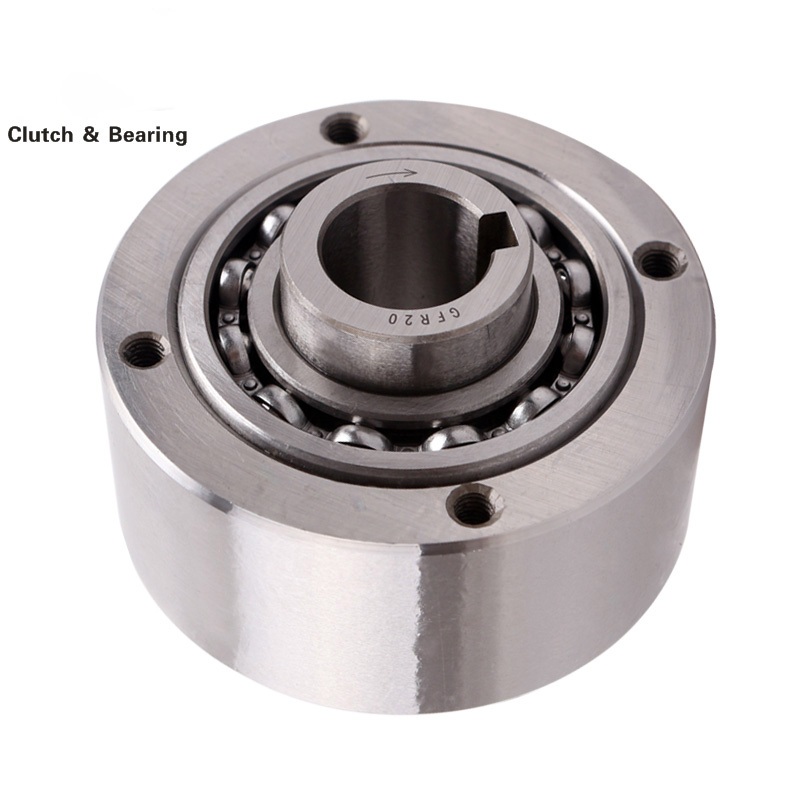
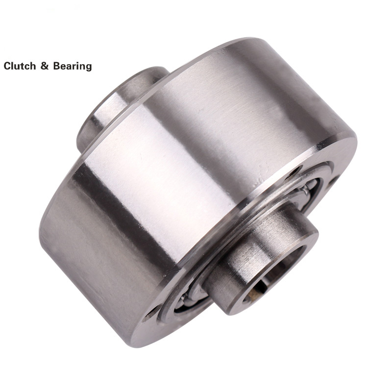
CLUTCH RELEASE BEARING
provisions to guide the fork or piston radially.
Our compact design combines a precision sheet metal bearing unit and polymer sleeve or carrier, for manual gearbox applications against a dry clutch. We offer multiple designs with inner or outer ring rotation for a variety of applications.
The units are designed to account for many constraints, including: automated manual transmission or dual clutch transmission. higher operating temperature; and increased application loads.
2.White box and carton
3.Customer brand design


Clutch Bearing,Auto Clutch Release Bearing,Clutch Release Bearing,Clutch Bearing For Auto
Shijiazhuang Longshu Mechanical & Electrical Equipment Trading Co., Ltd. , https://www.longsbearings.com