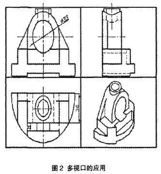
When drawing the ribs as shown in Figure 2, draw a rib in the isometric drawing, then switch to the top view and draw the second rib by mirroring. As you can see, combining these views to draw graphics simplifies the drawing process. This method of drawing graphics is also a method of generating a three-view prototype from a three-dimensional entity.

2.2.4 Proficiency in the use of solid face, edge, body editing commands
In addition to the editing operations such as moving, copying, deleting, chamfering, and rounding in 2D graphics, you can also edit the faces, edges, and bodies of solid objects, such as stretching, moving, and shifting. Copying, rotating, or tilting the solid surface, you can also copy the solid edges, and you can perform Boolean operations on the entities, such as cutting, cutting, and shelling. These functions make it easy for users to modify existing entities to form new features. . Flexible use of entity editing features will greatly improve modeling efficiency. Example: In the 3D solid modeling of Figure 2, the cylinder of Book 33ram is drawn in two ways: one is to draw the center of the bottom of the U-shaped solid as the center point of the bottom surface of the cylinder, and draw a cylinder with a height of 38ram; The center of the front surface of the U-shaped solid is the center point of the bottom surface of the cylinder, and a cylinder with a height of -30 mm is drawn, and then the editing operation of "moving 匾" or "stretching surface" is performed, and the front end surface is selected along the Z axis. Move or stretch 8mm in the direction.

2.2.5 Flexible use of the stretch and rotate commands to generate 3D solids from 2D graphics
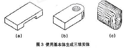
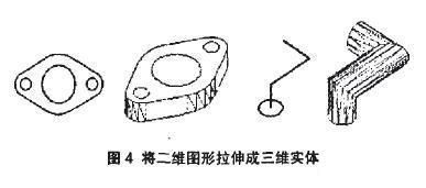
In AutoCAD, any complex entity can generally be seen as being formed by stacking, cutting, etc. of several simple entities. For simple entities of rules, you can use primitives such as cuboids, spheres, cylinders, cones, and wedges, and generate them by Boolean operations such as parallel, intersection, and difference. Fig. 3(a) shows a simple entity obtained by performing a difference operation between two rectangular parallelepipeds, and Fig. 3(b) shows a simple entity obtained by performing a difference operation between a rectangular parallelepiped and a cylinder and then performing a difference operation with another cylinder. Fig. 3(c) shows a simple entity obtained by performing an intersection operation between two cylinders and then performing a difference operation with another cylinder. For an irregular simple entity, first switch to the corresponding view plane, draw its plane graphic, and after forming the area, the plane graphic can be generated by stretching it along the vertical direction according to the specified height or path, as shown in Figure 4. Show.

Previous page next page
Pull Down Faucets,Pull Down Faucets Price,pull down kitchen faucet
Yuyao Zelin Sanitary Ware Co., Ltd , https://www.kitchen-sinkfaucet.com