The main electrical wiring of the photovoltaic power station is mainly the main electrical connection of the booster station, which is also called the primary electrical connection. It refers to the primary electrical equipment such as transformers, circuit breakers, disconnectors, arresters, transformers, capacitors, busbars, and power cables. Circuits that are connected in a certain order are usually represented by a one-line diagram.
When making electrical design once, it is necessary to fully consider factors such as power supply reliability, operational flexibility, ease of operation, economy, and ease of expansion.
The typical electrical main wiring can be roughly divided into two categories: according to the number of access points, there are bus wiring modes (ie, single access point) and no bus wiring (multiple access points). Among them, the bus bar connection mode is divided into single (double) bus and single (double) bus segmented two ways, no bus bus wiring can be divided into external bridge line mode and inner bridge line mode.
First, a bus bus wiring
1 single bus wiring
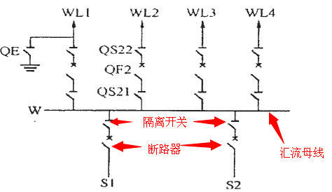
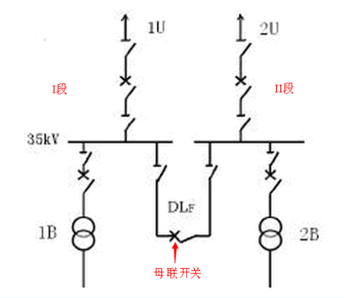
The advantages of single busbar connection are simple and clear wiring, less equipment, less investment, convenient operation and operation, and favorable for expansion. Disadvantages of the single busbar connection: poor reliability and flexibility, disconnection of all power supply when the busbar or busbar disconnector is in overhaul or fault.
2 double bus wiring
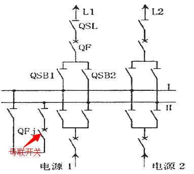
The busbars of the two groups are connected by a bus tie breaker. Each of the outlets and the power branch is connected to two busbars via a circuit breaker and two sets of busbar disconnectors.
Advantages of the double busbar connection: no influence on the normal power supply when overhauling any busbar; only affect the power supply of this branch circuit when the busbar disconnector is overhauled (the disconnector cannot be switched off with load and needs to be broken before the circuit breaker can be disconnected); all the work busbars fail Branches can quickly restore power supply; when special needs can be used to bus tie breakers and systems for simultaneous parallel and disjunctive operations, so the operation of the scheduling flexibility, high reliability, the same, equipment input costs higher.
Second, no bus bus wiring
Unit wiring
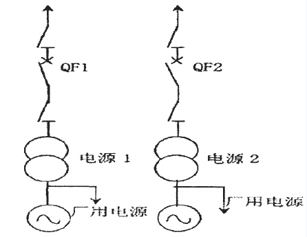
The connection of the power generation unit outlet directly to the high voltage system via the transformer is called the power unit-transformer unit unit wiring. On this basis, the high-voltage side of each main transformer is directly connected to a transmission line, transmitting power separately, no switching station is installed in the power plant, and each station's main transformer has no electrical connection. It is called generator-transformer-line unit. wiring.
Advantages of the unit wiring: simple wiring, less switchgear, less land occupation, easy operation, low voltage of the generator and the main transformer to measure the short-circuit current is reduced (because the power point of feedback is less), especially its investment can be reduced to the minimum .
2. Bridge wiring
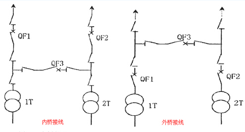
The so-called inner and outer bridging lines are based on the distance between the bridge (circuit breaker QF3 in the figure) and the transformer. The distance is called the inner bridge, the distance is called the outer bridge, and the main circuit breaker is connected to the unit in the distance. QF1, QF2) is the basis for judgment.
The inner bridge line is suitable for frequent line maintenance, and the transformer does not need to be frequently switched (the switching operation during transformer switching is more complicated, and it needs to cut off QF1 and QF3 at the same time).
The external bridging line is suitable for situations where the line is short and the transformer needs to be switched frequently, and the booster station has passing power through.
Third, the cost comparison

The above-mentioned several kinds of schemes, the investment cost of the equipment from high to low in the end is the double busbar wiring method, single busbar subsection method, bridge wiring method, unit wiring, single busbar wiring (the unit wiring method is suitable for multiple access points, repeated input than single Busbar connection high).
IV. Main Electrical Wiring Features of Photovoltaic Power Plants
Photovoltaic power plants are located at the end of the power grid. The installed capacity is small. Input and output have no impact on the stability of the system. Therefore, the photovoltaic power station can be put into power generation at any time and cut out. Therefore, at the time of design, the requirement for the reliability of the power transmission of the photovoltaic power plant is not a priority.
In principle, all the above schemes are applicable to the main electrical wiring of photovoltaic power plants. However, considering the economic benefits and the number of access points, photovoltaic power plants should give priority to the option of relatively low investment. Therefore, the main electrical wiring of photovoltaic power plants can be unit wiring, bridge wiring or single busbar wiring.
The LED Ceiling Light is widely used at Office, shopping mall, Hotel, showroom and so on.
The advantages for DiLin LED Ceiling Light
1. Fashion design with high quality of aluminum housing and constuction to make sure the cooling of LED Ceiling Light good enough.
2. High quality of COB and driver solution to make sure LED Ceiling light quality stable enough.
3. Strong Engineer & QC team are good at customizing and offer flexible solution for competitive Ceiling light.
4. Fast lead time: 5-7days for samples and 15-25days for bulk order.
5. 3 or 5 year warranty with standardized after-sale serivce process.
Led Ceiling Light,Ceiling Light Fixtures,Cone Ceiling Light,Ceiling And Wall Light Kits
Jiangmen Dilin Lighting High-Tech Co., Ltd. , https://www.jmdilinlighting.com