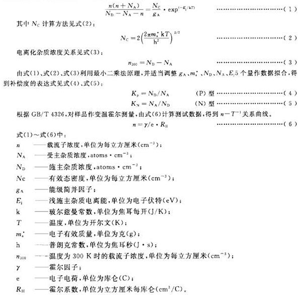
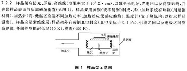
1 Scope This standard specifies the measurement and analysis methods for the compensation of silicon materials for photovoltaic cells. This standard applies to the measurement and analysis of the degree of compensation of non-doped silicon materials for photovoltaic cells. 2 normative references The following documents are indispensable for the application of this document. For dated references, only dated versions apply to this document. For undated references, the latest version (including all amendments) applies to this document. GB/T 4326 extrinsic semiconductor single-crystal Hall mobility and Hall coefficient measurement method GB/T 14264 Semiconductor Material Terms GB/T 24581 Determination of Group III and V Impurities in Silicon Monocrystals by Low-Temperature Fourier Transform Infrared Spectroscopy GB/T 29057 Procedure for evaluating polycrystalline silicon rods by zone melting and crystal analysis 3 Terms and Definitions The terms and definitions defined in GB/T 14264 apply to this document. 4 method principle Based on the electrically neutral equation of the relationship between carrier concentration and temperature changes, a computer fitting analysis of the n(P)-T-1 relationship curve was performed to obtain a compensation degree. The electric neutral equation (taking an N-type sample as an example) is shown in equation (1): 5 Interference factors 5.1 The accuracy of the test temperature directly affects the accuracy of the measurement results. 5.2 The electrode should have good ohmic contact to ensure the accuracy of the measurement. 5.3 For polysilicon samples, the zone melt pull process and the sampling site will affect the evaluation of polysilicon. 6 Environmental conditions 6.1 The temperature is 15°C-28°C. 6.2 Relative humidity should not exceed 65%. 6.3 Testing The shielded room should be free from mechanical conflicts, vibrations, and high-power electrical equipment without electromagnetic interference. 7 Instruments and Equipment 7.1 Hall Test System 7.1.1 Constant current source Provide current for the sample, the current stability should be better than ± 0.5%. 7.1.2 Voltmeter To measure the voltage of the sample, the accuracy should be better than ±0.5%, and the input impedance of the voltmeter should be more than 10000 times of the impedance of the tested sample. 7.1.3 Magnets The magnetic flux density should be in the range of 0.2T-1.0T. Within the range of the sample, the magnetic flux density uniformity should be better than ±1%. 7.1.4 Switch Matrix Used to change the current flow direction of the sample and measure the voltage of the opposite electrode. The switch matrix should have good insulation and reliability. 7.2 sample room 7.2.1 The sample chamber consists of a cryogenic device, a temperature measuring device, and a sample holder. The sample chamber should be composed of non-magnetic materials, temperature adjustable and can guarantee a certain degree of stability of the sample temperature. If the heating device is heated by a resistance wire, attention should be paid to the winding and placement of the resistance wire so as to prevent the resistance wire from generating a magnetic field perpendicular to the surface of the sample during the energization process. 7.2.3 The temperature range of the cryogenic device is 10K-400K. The precision of temperature control should be better than ±0.05K. The temperature sensing element of the temperature measuring device should be as close to the measured sample as possible to ensure the consistency of the measuring temperature and the sample temperature. 8 sample preparation 8.1 single crystal measurement sample According to GB/T 4326, the single crystal silicon measurement sample is processed, ultrasonically cleaned, dried, and used. 8.2 Polycrystalline Measurement Samples According to GB/T 29057 polycrystalline silicon rod samples were prepared into single crystal silicon, and in accordance with the provisions of the above standard sampling position, cut into a thickness of 1mm wafer, according to the requirements of Van Debao sample wafers prepared into a measurement sample, ultrasonic cleaning Let it dry and wait. 8.3 ohm electrode preparation The electrode of the measurement sample is prepared by techniques such as evaporation and sputtering. The electrode size should be as small as possible (preferably point contact) and close to the edge without affecting the normal lead out of the electrode lead, and should be as symmetrical as possible in the sample. Prepare the electrode (make sure the electrode is in ohmic contact with the sample). 9 test steps 9.1 Strong samples to be tested Prevent the sample from being placed on the sample rack. The seal is placed in the refrigeration system of the secondary physical examination. It should be in the center of the magnetic pole and the magnetic field should be perpendicular to the surface of the sample. 9.2 start the vacuum pump, when the vacuum reaches 0.1Pa, open the low temperature system. 9.3 Select the starting temperature according to the sample requirements and perform temperature control. After the temperature is stable, add a magnetic field to measure the Hall coefficient. 9.4 set the next temperature point, until the temperature is stable, repeat 9.3 steps, until the determination of the complete temperature zone, to get nT-1 relationship curve. 9.5 In order to reduce the error, the variable temperature measurement should be dense in the low temperature area, and the nT-1 curve needs to show a clear de-ionization process (the curve is smooth, and no distortion appears). 10 data processing 10.1 The measurement data obtained at different temperatures shall be calculated according to Equation (6), and the gamma factor shall be equal to 1 for correction. 11 Precision 12 report At a minimum, the report should contain the following: a) Sample delivery unit and sample delivery date; b) sample name, specification and number; c) instrument type; d) measuring environment; e) measurement results, including compensation and relationship curves; f) operator, measurement date, measurement unit. Steel Precision Machining Components Steel Precision Machining Components,Steel Cnc Machining Parts,Cnc Machining Steel Parts,Cnc Precision Machined Components Stand Dragon Industrial Co., Ltd. , https://www.standdragontw.com


Photovoltaic battery silicon material compensation degree measurement method (GB/T 29850-2013)