Classification of typical drawing die, the structure, the main function of modern automobile parts <br> <br> stamping die can be divided into the following categories: trimming die and the subsequent draw die, the die punching, flanging die, A mold that has four functions, such as a shaping die. These four types of subsequent molds are also equipped with auxiliary mechanisms such as wedges, wedges and rotating mechanisms. 2. The structure of the drawing die can be seen from the structural drawings of the above three drawing die. The main structure of the drawing die is three by the punch, the die, the presser (pressing ring, pressing plate) The main work component is composed. 2. Main technical requirements and treatment methods in commissioning In the past, the pressing surface was studied, and only the coloring of the entire pressing surface was studied. The sectioned strip is thickly partially ground, the punch and the die are gapped, and then the mold is debugged. In this way, the drawing die takes a long time to occupy the equipment, and it is impossible to confirm the drawing property of the entire drawing die and the process replenishment in advance. According to the statistics and cause analysis of the drawing and manufacturing process of the drawing die, and learning from the experience of foreign mold manufacturing, the existing working standards and assembly and debugging methods are improved. Calcium Fluoride Bi-convex Lenses
Calcium Fluoride Bi-convex Lenses,N-BK7 Bi-convex Lenses,bi-convex lens,bi convex lens,focal length of biconvex lens
Our company can produce many kinds of flat convex Spherical Mirrors with different sizes, radii and base materials, flat convex spherical Mirrors, flat concave spherical mirrors, double convex spherical mirrors, double concave spherical mirrors, meniscus spherical mirrors and other ordinary spherical mirrors. Special spherical mirror can also be processed, such as: achromatic spherical mirror, aspheric surface and spherical mirror group.
Calcium Fluoride Bi-Convex Lenses,Spherical Aspheric Lenses,Magnification Lenses,Glass Slides Microscope Gold Dragon Optics Electronic Technology CO.,Ltd , https://www.golddragon-optics.com
1. Drawing die classification The drawing die is mainly classified into single-action drawing die (Fig. 1), double-action drawing die (Fig. 2) and three-moving drawing die (Fig. 3). 
Figure 1 Single-action drawing die 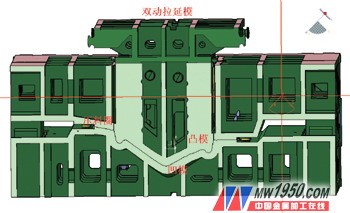
Figure 2 Double-action drawing die 
Figure 3 Three-motion drawing die
3. The main functional part of the drawing die is the convex R and the pressing surface. Therefore, the gap adjustment of the fitter and the debugging is mainly concentrated in these two parts. The adjustment of the façade gap is used as a means to correct the machining accuracy. With the continuous improvement of the processing equipment and the improvement of the numerical control processing quality, the adjustment workload of the façade gap has gradually disappeared.
Main technical problems and solutions in the assembly process
Some profile quality defects generated during the drawing die assembly process bring a lot of repetitive work to the post-compression work of the drawing die, and some quality defects even affect the drawing member and the final quality of the workpiece.
Based on years of experience in the assembly and commissioning of drawing die, the author summarizes the following solutions to the problems and problems that arise during the assembly and commissioning of the drawing die.
1. Problems (1) The method of Dawning is not scientific With the development of science and technology, the existing CNC machining equipment has replaced the previous copy milling machine, and the precision of the equipment used for processing the mold is getting higher and higher, the surface of the mold The processing quality is getting better and better, and the previous mold calendering method can no longer meet the existing mold manufacturing. In the past, the work of twilight only flattened and brightened the mold, ignoring the influence of twilight on the precision of the mold profile. Through the analysis of the statistical data in the work, the following results were obtained, and the pressing surface of the range of 15 mm × 150 mm was lighted with 120# red whetstone, and the surface was lowered by 0.1 mm in 15 minutes. It can be seen that many of the training work during commissioning is caused by the flaw in the quality of the profile due to the incorrect method of twilight.
(2) The selection of the reference is incorrect. Before the drawing die is used, the punching die and the pressing ring are used first. The upper device is used to grind the die pressing surface, ignoring the choice of the die manufacturing benchmark. The die of the drawing die is qualified by the CNC milling machine at one time, and the geometrical accuracy of the die is very high. However, the pressing surface of the die is damaged by the pressing ring as the reference, which will destroy the geometric size and ultimately affect the overall size requirement of the drawing member. , the post-sequence trimming positioning brings the profile deviation, which will seriously cause defects such as crushing and unstable positioning.
2. Solution (1) Dawning technology standard Dawning should refer to the CNC milling cutter trace light to ensure that 10 to 15 points of CNC milling cutter marks are evenly retained per square inch, which can effectively ensure the mold surface precision. Before the device is placed, the convex R is dimmed to meet the surface roughness requirement during debugging.
(2) The reference is to select the pressing surface of the punch and the die of the drawing die when the calendering is selected, and the punching die is used as the benchmark for the whole set of the mold, and the pressing surface of the die is used as the benchmark for the pressing surface. The overall geometric accuracy of the mold can be guaranteed. The drawing piece can be directly debugged after the grinding of the pressing surface.
Work points for commissioning 1. Work before commissioning Read and understand the product formability analysis report before commissioning. It provides theoretical guidance for determining the nature and properties of wrinkling and cracking, which is helpful for determining the correct solution.
The commissioning personnel can compare the contact state of the sheet in the initial stage of drawing during the commissioning according to Fig. 4, and analyze whether the forming defect is caused by the poor contact state of the sheet material. Fig. 5 is a view showing the formability of the drawing member at the end of drawing. Green indicates sufficient deformation and good formability; gray indicates insufficient deformation; purple indicates compressive stress; red indicates cracking. This is used as a theoretical guide for the comparative analysis of the quality problems of the drawn parts during commissioning. 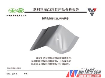
Figure 4 Shape of the sheet when the die and the binder ring are closed
Figure 5: Drawing and drawing of the forming part of the drawing
(1) Important training area definition When testing the pressing surface, it should ensure that the coloring ratio between the pressing material and the concave die is over 95%, and the coloring rate of 25mm outside the pressing material is more than 80%. It should be ensured that the coloring ratio of 40 mm outside the die mouth is 95% or more. Other parts should be gradually opened to reduce the amount of training work.
(2) The operation method requires that the pressing surface should basically meet the requirements, and the side surface should be polished. When the coloring rate of the pressing surface meets the requirements, the surface roughness should also meet the requirements, avoiding the second glare after the equipment is replaced. The failure of the coloring rate of the binder surface affects the debugging work of the mold. After the grinding of the pressing surface, the first commissioning of the drawing die can be carried out directly on the equipment. In this way, it can be confirmed in advance that the drawing of the drawing die and the replenishment part of the process are reasonable, and at the same time, some auxiliary methods (commonly used sanding cloth, pad plastic cloth, drawing oil, etc.) can be used to debug the drawing die for grinding. Research piece. After the equipment under the mold, the mold can be modified and improved according to the state of the mold member to ensure that the second debugging work is carried out after the drawing of the drawing die.
(3) Adjustment of quenching process According to the work experience, the quenching work of the drawing die should be carried out after the qualified parts of the mold are debugged. If the quenching will bring certain processing difficulties to the later debugging, it will reduce some need to increase. The hardness of the R part, the secondary quenching will produce a quality defect of unacceptable local hardness.
Conclusion
The production of modern automobile body parts has higher and higher requirements on the quality of the molds. Only when the requirements of the users are met, the molds produced can have its market, so no errors are allowed in the various technical aspects of mold manufacturing. In particular, the last technical link (the assembly and debugging of the mold) can not be mistaken, otherwise our preliminary work may be abandoned. Therefore, with the rapid development of manufacturing technology, the mold assembly and debugging technology will be continuously improved and improved. Thereby meeting the needs of automotive mold production.
Materials: optical glasses such as flint glass, ultraviolet fused quartz and infrared fused quartz, as well as optical crystal materials such as calcium fluoride (CaF2), germanium (Ge), Zinc selenide (ZnSe) and silicon (Si)
Focal length: ±5mm -- ±1000mm±1%
(Germany TIROPTICS OPTOMATIC2000 test)
Outer circle: 4mm -- 200mm±0.1mm
Center thickness tolerance: ±0.1mm
Center deviation: 3-5 points
Surface accuracy: /2@
Surface quality: 40/20
Effective diameter: 90%
Plating film: according to customer requirements can be coated
In addition, we have more than a thousand kinds of standard products, and some of the standard products in stock to meet your needs

Automobile body cover drawing die assembly and debugging